Overview
This page contains more descriptive explanations for filling in certain fields in a GeMS database. Text on this page is taken directly from the GeMS document. Text deemed the most useful has been bolded.
The values in certain fields must be defined in the Glossary table. These fields are highlighted in magenta in the descriptions that follow.
IdentityConfidence and ExistenceConfidence
According to the FGDC cartographic standard (FGDC, 2006), scientific confidence may have either a single dimension or multiple dimensions. For a map-unit area, scientific confidence will have one dimension (that is, confidence that the map unit is correctly identified). In the case of faults, contacts, and other feature traces, the situation is more complex. For example, uncertainty may arise as to whether a boundary between two units is a contact or fault, or what kind of fault is mapped; in both cases, this uncertainty would be specified by an identity confidence value. In some cases, however, one may suspect (but not be certain) that a fault is present. Similarly, one may map features such as fold-hinge surface traces, dikes, and marker beds where their existence is suspected but not certain. These uncertainties would be specified by an existence confidence value such as “questionable”. Note that contacts rarely are mapped where their existence is uncertain; if different map units are identified, a boundary of some sort must exist between them, and so the identity of that boundary may be questionable, but not its existence.
GeMS includes ExistenceConfidence and IdentityConfidence fields for line feature classes and an IdentityConfidence field for polygon and point observation features. We discussed at length whether to combine these confidence concepts into a single ScientificConfidence field in the database, perhaps with four or six values that would allow for various combinations of existence and identity confidence, but we decided that it makes more sense to separate them, as is specified in the FGDC cartographic standard. In many situations, default values for an entire map area would be appropriate, as is noted elsewhere in this report; in other situations, perhaps tools to efficiently assign varying confidence values can be developed by the GeMS user community. We expect that symbolization will, in many cases, be assigned on the basis of the appropriate confidence terms and feature type.
For most databases, all values of ExistenceConfidence and IdentityConfidence likely will be either “certain” or “questionable” (see table 2), although GeMS allows values and definitions other than these. Values of ExistenceConfidence and IdentityConfidence must be defined in the Glossary table. For some digital transcriptions of legacy or paper geologic maps, it may not be possible for the transcriber to assign values of ExistenceConfidence or IdentityConfidence; in these cases, the value of “unspecified” should be used. Note, however, that if a reviewer during the review process encounters a value of “unspecified” in a database of new mapping, its use should be questioned.
Table 2. Example picklist of values for the IdentityConfidence field.
[Definitions modified from FGDC cartographic standard (Federal Geographic Data Committee, 2006), p. 16–17, A-iii]
| Value | Definition |
|---|---|
| certain | Identity of a feature can be determined using relevant observations and scientific judgment; therefore, one can be reasonably confident in the credibility of this interpretation |
| questionable | Identity of a feature cannot be determined using relevant observations and scientific judgment; therefore, one cannot be reasonably confident in the credibility of this interpretation. For example, IdentityConfidence = “questionable” would be appropriate when a geologist reasons, “I can see some kind of planar feature that separates map units in this outcrop, but I cannot be certain if it is a contact or a fault" |
OrientationConfidenceDegrees
For orientation measurements (bedding, foliation, lineation, joints, etc.), it is useful to describe how accurately the orientation has been measured. For linear features (for example, fold axes, lineations), this error is usefully expressed as the radius of the error circle, similar to the alpha95 value often reported for paleomagnetic directions. For planar features (for example, bedding, foliation), the error is that of the pole to the plane. The OrientationPoints feature class includes an OrientationConfidenceDegrees field to record this uncertainty. Values of OrientationConfidenceDegrees are recorded as floating-point numbers because they are real, measurable quantities, not because they are precisely known.
LocationConfidenceMeters
Reported locations of geologic features and observation points commonly are uncertain for a number of reasons. For example, (1) there may be error in locating observation points because of global positioning system (GPS) errors or an imprecise base map, (2) positions of subtle features may be poorly known relative to well-located observation points, or (3) the locations of features may be known only by inference from locations of other features or observations. This uncertainty could be expressed as uncertainty in absolute location (geodetic accuracy); however, because uncertainty in absolute location often is unknown (especially with legacy data), because most users locate geologic features in relation to a base map, and because most spatial analyses of geologic map data are in relation to the base map or to other data in the same database, we’ve chosen to focus on uncertainty of location relative to the positions of other features in the database (for example, “How well located is this contact with respect to surrounding lithologic and strike-and-dip observations?”). With a sufficiently large database, this is equivalent to uncertainty in location relative to the base map.
We define locational confidence (contained in the database field LocationConfidenceMeters) as the combination of the positioning error of a known point relative to the base map (“How precisely do I know where I am?”) and the uncertainty in location of a geologic feature relative to that known point (“How precisely, relative to where I am, can I place this contact?”). For a well-exposed, sharp contact, the second factor would be zero, and the locational confidence becomes equivalent to the positioning error.
This usage differs from that advocated by Section 4.2 in the introductory text of the FGDC cartographic standard (FGDC, 2006), which suggested that spatial accuracy be expressed using the following three attributes: (1) locatability (values of “observable”, “inferred”, or “concealed”); (2) zone of confidence (value of a distance [for example, a value equivalent to one-twenty-fifth of an inch at map scale], which may or may not be the same for all parts of a map); and (3) positioning (values of “within zone of confidence” or “may not be within zone of confidence”). We have departed from the recommendation in the FGDC cartographic standard in order to create databases that are simpler to understand and are less dependent upon visualization scale. In addition, we believe our approach is more informative because the FGDC cartographic standard does not include guidance for quantitatively recording how precisely a feature is located if it is not positioned within the zone of confidence.
For point features, LocationConfidenceMeters should be reported as the estimated radius (in meters) of the circle of uncertainty around the point location. For line features, it should be the half-width of the zone within which a line is asserted to be located. Values of LocationConfidenceMeters are recorded as floating-point numbers because they are real, measurable quantities, not because they are precisely known. Table 1 shows an example picklist of values for the LocationConfidenceMeters field that may provide insight into how this field may be populated. Note that the values in this picklist (table 1) are merely suggestions; use of other values for LocationConfidenceMeters certainly is acceptable. In situations where locational confidence changes along the length of a line, it may be best to split the line and assign different values of LocationConfidenceMeters to the different line segments.
Table 1. Example picklist of values for the LocationConfidenceMeters field.
[Abbreviations: DEMs, digital elevation models; GPS, global positioning system; m, meter(s); NAIP, National Agriculture Imagery Program]
| Example value (m) | Comments |
|---|---|
| 5 | Appropriate for well-defined features located in the field by clear-sky GPS, by inspection of high-resolution topography (for example, 1- or 2-m-resolution lidar DEMs), or by inspection of large-scale, well-rectified digital orthophotographs (for example, NAIP images) |
| 25 | Reasonable for locations established by inspection of 1:24,000-scale maps, or for “accurately located” features digitized from 1:24,000-scale paper source maps |
| 50 | May be appropriate for some “approximately located” lines on 1:24,000-scale maps; other “approximately located” lines on the same map may have values of 100 m or more |
| 100 | Appropriate for “accurately located” features digitized from 1:100,000-scale paper source maps |
| 250 | Appropriate for “accurately located” features digitized from 1:250,000-scale paper source maps, or when a geologist, working at 1:24,000 scale, says, “My confidence in locating this feature is exceptionally low” |
Values of LocationConfidenceMeters can be visualized with semitransparent, proportional-width symbols (similar to buffers in GIS jargon) in which the half-widths of the semitransparent symbols are equal to the LocationConfidenceMeters values assigned to the features. Such visualizations are powerful tools for evaluating the appropriateness of LocationConfidenceMeters values as a map is being prepared.
When new geologic map databases are created, we expect that geologists will assign values of LocationConfidenceMeters to individual features or groups of features on the basis of their knowledge of mapping procedures, field conditions, and the nature of specific features. Even with, for example, a factor-of-two uncertainty, such values assigned by the original mapper or author are preferable to a null value. When transcribing legacy maps, an experienced field geologist will commonly be able to estimate useful values for LocationConfidenceMeters. In rare cases, such estimation may not be practical, and, in such cases, traditional qualitative descriptors of line accuracy such as “contact, approximate” may be placed in the Type field; the meanings of such qualitative descriptors must be defined in the Glossary table. A null value (for example, value = −9; see discussion below) may then be assigned to LocationConfidenceMeters; note that this a numeric value, not a text string.
For certain types of lines (for example, most map boundaries), positions are calculated or assigned, not observed. For these lines there is no positional uncertainty, and LocationConfidenceMeters should be assigned a value of 0.0.
GeoMaterialConfidence
We have added the fields GeoMaterial and GeoMaterialConfidence to the DescriptionOfMapUnits table in order to provide abbreviated content that will allow for simple queries and (or) generalized symbolizations of the character of geologic map units across one or many maps. It is important that users populate the GeoMaterial field with terms from the NGMDB standard term list (included in appendix 1); they should then use the GeoMaterialConfidence field to characterize the relative appropriateness of the term chosen for the GeoMaterial field. Note that the abbreviated content in the GeoMaterial field is not a replacement for the full, robust, free-text information in the Description field. Note also that additional, more detailed lithologic information may be included either in a supplementary user-defined table or in the optional StandardLithology table (see discussion in appendix 2, “Optional Elements”).
We recognize that such a classification cannot completely address the immense variety of map units present across the Nation, and we expect that other regionally specific classifications of map units will be developed that are more appropriate to local conditions. The appropriateness of a selected GeoMaterial term for describing a map unit is specified by values in the GeoMaterialConfidence field (see table 1–1), which provide the map user with a potentially useful qualifier term (please refer to the Geologic Materials discussion in the “Design Considerations” section, above).
Table 1-1. Values (and their definitions) that populate the GeoMaterialConfidence field in a DescriptionOfMapUnits table.
[Note that, when creating a new database, the script GeMS_CreateDatabase_Arc10.py (available at https://github.com/usgs/GeMS_Tools) or its replacement inserts these GeoMaterialConfidence terms and definitions into Glossary table. See also, table 14]
| Term | Definition |
|---|---|
| High | The selected term in the GeoMaterial field (and its definition) adequately characterizes1 the overall lithologic nature of rocks and (or) sediments in the map unit |
| Medium | The selected term in the GeoMaterial field (and its definition) generally characterizes the overall lithologic nature of rocks and (or) sediments in the map unit, but one or more significant but minor lithologies are not adequately described by the selected term |
| Low | Either (1) the overall lithologic nature of rocks and (or) sediments in this map unit is not adequately classifiable using the available list of GeoMaterial terms (and their definitions), but the selected term is the best available, or (2) this map unit is not sufficiently known enough to confidently assign a GeoMaterial term |
Symbol
The Symbol field specifies either a point symbol (sometimes called a marker symbol), a line symbol, or an area-fill symbol (a color and (or) pattern fill) for the feature (for example, a dot for a potassium-argon age locality; a heavy black line for a fault; a pale-yellow color fill for a polygon of alluvium). Null values (which would indicate a point, line, or polygon is not shown/filled on the map) are permitted.
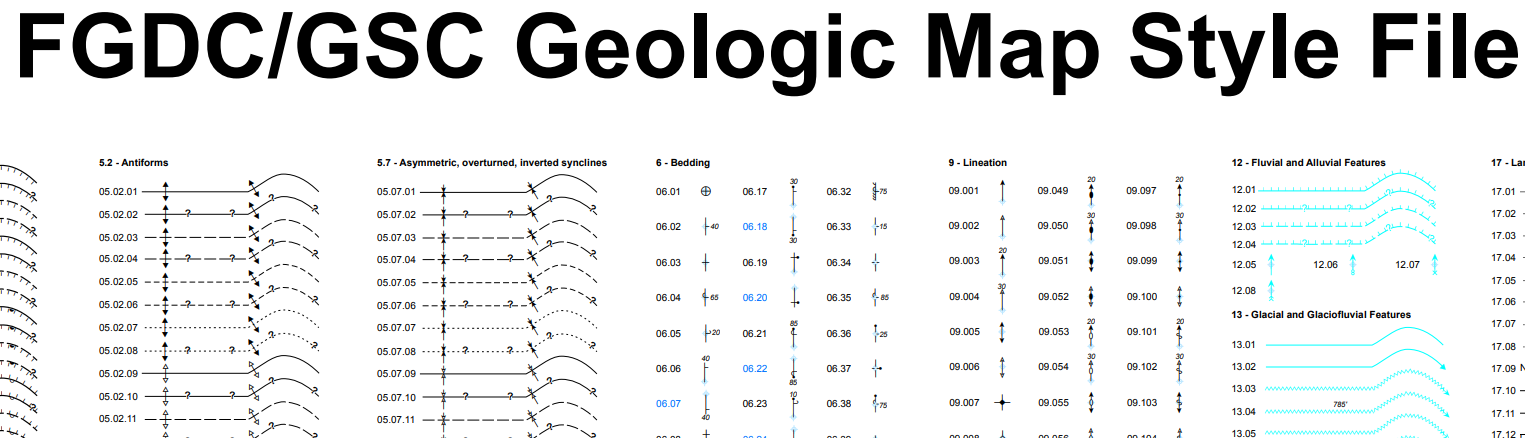
Point and Line
Generally speaking (and to the extent that it is possible), line and point symbolization should follow the FGDC Digital Cartographic Standard for Geologic Map Symbolization (FGDC, 2006). Most of the symbols in the FGDC cartographic standard have been implemented as an ArcGIS .style file (“FGDC_GSC_20100414.style”) by members of the Geological Survey of Canada; this .style file and its associated font files are available under the Resources heading at the GeMS website (https://ngmdb.usgs.gov/Info/standards/GeMS/). Note that both the .style file and all its associated font files need to be installed for the .style file to function correctly. Note also that, to use this .style file, it is necessary to left-pad the original FGDC symbol identifiers with zeroes so that each part of the identifier has a two- or three character width (for example, symbol 1.1.3 becomes 01.01.03, and symbol 1.1.25 becomes 01.01.25).
Polygon
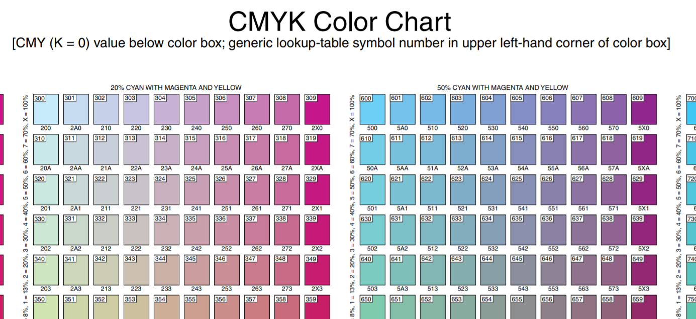
Values can be indices to colors selected from the FGDC cartographic standard’s CMYK Color Chart (Federal Geographic Data Committee, 2006). An ArcGIS .style file (“FGDCcmyk.style”) of this chart is available under the Resources heading at the GeMS website. The symbol field in the MapUnitPolys feature class can be assigned by joining to the symbol field in the DescriptionOfMapUnits table.
If the FGDC cartographic standard does not define a suitable symbol for a particular feature on a map, the standard may be supplemented with either customized symbols or with FGDC symbols that have been repurposed for the map. Such repurposed symbols need to be identified in the RepurposedSymbols table, which is required if FGDC symbols have been repurposed.
Table 32. Fields in RepurposedSymbols (an as-needed nonspatial table).
[Abbreviation: FGDC, Federal Geographic Data Committee]
| Field name | Description | Notes |
|---|---|---|
| FgdcIdentifier | Zero-padded identifier string (derived from identifier in FGDC cartographic standard) | Example of value is “01.01.03” (original FGDC identifier was “1.1.3”). Null values not permitted |
| OldExplanation | Original symbol description from FGDC cartographic standard | Example of value is “contact--identity and existence certain, location approximate”. Null values not permitted |
| NewExplanation | Symbol usage as repurposed on this map | Example of value is “limit of tephra deposits from Holocene eruptions of Glacier Peak”. Null values not permitted |
| RepurposedSymbol_ID | Primary key | Examples of values are “RSY1”, “RSY2”. Values must be unique in database. Null values not permitted |
HierarchyKey
Map-unit explanations on geologic maps commonly are ordered and hierarchical: map units are listed in an intentional sequence; they usually are listed under headings and subheadings; and some may be subunits of other map units. The sequence of map units shown in a DMU generally corresponds to the relative ages of map units, from youngest to oldest. This same hierarchy also is commonly expressed in a Correlation of Map Units (CMU) diagram. Hierarchy also may express closeness in genesis, paleogeography, relative certainty of map-unit identification, or other relations. On some maps that organize the DMU by the various physiographic regions or geologic terranes, or where many units were deposited contemporaneously (for example, many surficial geologic maps), the rules for designation of hierarchy may appear somewhat arbitrary, but the hierarchy is evident from the ordering and indentation of the DMU.
In the DMU of a USGS geologic map, hierarchy is shown by the paragraph style (font style, alignment, and indentation) of successive elements. This hierarchy is also shown by the spatial arrangement of map-unit boxes, headings, and brackets in the associated CMU diagram. We record these relations in the DescriptionOfMapUnits table with the HierarchyKey attribute, which (1) allows the table to be sorted in its proper sequence, and (2) records parent-child relations. Values of HierarchyKey are text strings with the form of nn-nn or nn-nn-nn, etc. Each fragment (nn) of the HierarchyKey value is numeric, is left-padded with zeros so that each fragment has the same length, and is dash delimited. Different values of HierarchyKey may be made up of different numbers of fragments. For example, a DMU row that has a HierarchyKey value = “03-11” is the eleventh child of the parent row that has the HierarchyKey value = “03”.
The following are some general rules for the construction of HierarchyKey values:
- Within siblings (that is, children of the same parent), elements are numbered youngest to oldest
- A parent may have 0, 1, or many children
- The length (n versus nn versus nnn) of a HierarchyKey fragment is determined by the size of the family that has the largest number of siblings. Note that it is acceptable to have extra zeros (for example, using an unnecessarily long fragment value of “003”, when “3” or “03” would work), but this practice generally is discouraged as it reduces the readability of HierarchyKey values
- Headings cannot be children of map units; however, headings may be children of other headings, and map units may be children of either headings or other map units
- Values of HierarchyKey within a single DescriptionOfMapUnits table must be unique
- If an alphanumeric sort on the HierarchyKey field (in ascending order) does not put the DescriptionOfMapUnits table in the correct order (that is, if it does not match the order of the DMU), then one or more HierarchyKey values are incorrect
- After alphanumeric sorting, a HierarchyKey value may be the same length as its preceding value (that is, it is a sibling); or it may be one fragment longer than its preceding element (that is, it is a child) but not more than one fragment longer (generations cannot be omitted); or it may be shorter than its preceding value (that is, it is an aunt, a great-aunt, etc.; in other words, it is not in the immediate family)
- It typically is easier to decipher hierarchy from a DMU than from a CMU. Unfortunately, on some published maps, the hierarchy of headings and map units in the DMU and CMU do not agree, and it is not easy to determine which is correct. When encoding such maps, choose the hierarchy that you think best expresses the author’s intentions and will best serve users of the database.

Figure 3-4. Part of an older map-unit explanation, excerpted from an older geologic map (Scott, 1961), showing an older, abbreviated style of mapunit description. Click the figure to enlarge. See table 3–4 for parsing of headings and map units into DescriptionOfMapUnits table.
Table 3-4. Selected fields and values from a DescriptionOfMapUnits table for the explanation depicted in figure 3–4.
[Headings, map units, and unit names from Scott (1961). Note that formatting (capitalization, alignment, and perceived indentation) of Name values is shown for example purposes only, to help match them to headings and units shown in figure 3–4. Note also that title (“EXPLANATION”) is omitted]
| Field name | |||||
|---|---|---|---|---|---|
| HierarchyKey | ParagraphStyle | MapUnit | Name | ||
| 1 | DMUUnit1 | Qal | Alluvium | ||
| 2 | DMUHeading2 | <null> | MIDWAY GROUP | ||
| 2-1 | DMUUnit1 | Tc | Clayton Formation | ||
| 3 | DMUHeading2 | <null> | SELMA GROUP | ||
| 3-1 | DMUUnit1 | <null> | Providence Sand | ||
| 3-1-1 | DMUUnit2 | Kpu | Upper member | ||
| 3-1-2 | DMUUnit2 | Kpp | Perote Member | ||
| 3-2 | DMUUnit1 | <null> | Ripley Formation and Demopolis Chalk | ||
| 3-2-1 | DMUUnit2 | Kd | Demopolis Chalk | ||
| 3-2-2 | DMUUnit2 | <null> | Ripley Formation | ||
| 3-2-2-1 | DMUUnit3 | Kru | Upper member | ||
| 3-2-2-2 | DMUUnit3 | Krc | Cusseta Sand Member | ||
| 3-3 | DMUUnit1 | <null> | Mooreville Chalk and Blufftown Formation | ||
| 3-3-1 | DMUUnit2 | Km | Mooreville Chalk | ||
| 3-3-2 | DMUUnit2 | Kb | Blufftown Formation | ||
| 4 | DMUUnit1 | Ke | Eutaw formation | ||
Note the following in the above examples (fig. 3–4; table 3–4):
- There is no separate DMU in this report; map-unit descriptions are contained in the Explanation
- Unused fields (for example, the MapUnit field for headings) are filled with null values, not empty strings
- It is unclear whether Midway Group and Selma Group are headings or map units, but the hierarchy expressed in the Explanation is obvious, and the corresponding HierarchyKey values (“2”, “3”) are easily assigned. In this case, the ParagraphStyle values (“DMUHeading2”) were chosen somewhat arbitrarily
- The Explanation boxes (as read from left to right, top to bottom) show the Demopolis Chalk preceding the Ripley Formation, but the order of the associated text suggests the reverse. In this case, the HierarchyKey values (“3-2-1”, “3-2-2”) chosen reflect the box order.
AreaFillRGB
Specifies RGB equivalent of area-fill color of map unit as {<red value>,<green value>,<blue value>} tuples. Examples of values are “255,255,255”, “124,005,255”. Use of consistent syntax is important to enable computer programs to read field and display intended color: (1) each RGB color value is integer between 0 and 255; (2) values are left-padded with zeroes so that each consists of 3 digits; (3) values are separated by commas with no spaces (for example, nnn,nnn,nnn). Provided as convenience for users who want to re-create area-fill colors for onscreen viewing; especially important to non-ArcGIS users who are unable to use .style file supplied with database. Null values only permitted for uncolored map units and for headings.
AreaFillPatternDescription
Easily understood description of pattern fill of map unit (for example, “random small red dashes”). Provided as convenience for users who want to re-create area-fill patterns; especially important to non-ArcGIS users who are unable to use .style file supplied with database. Null values only permitted for unpatterned map units and for headings.